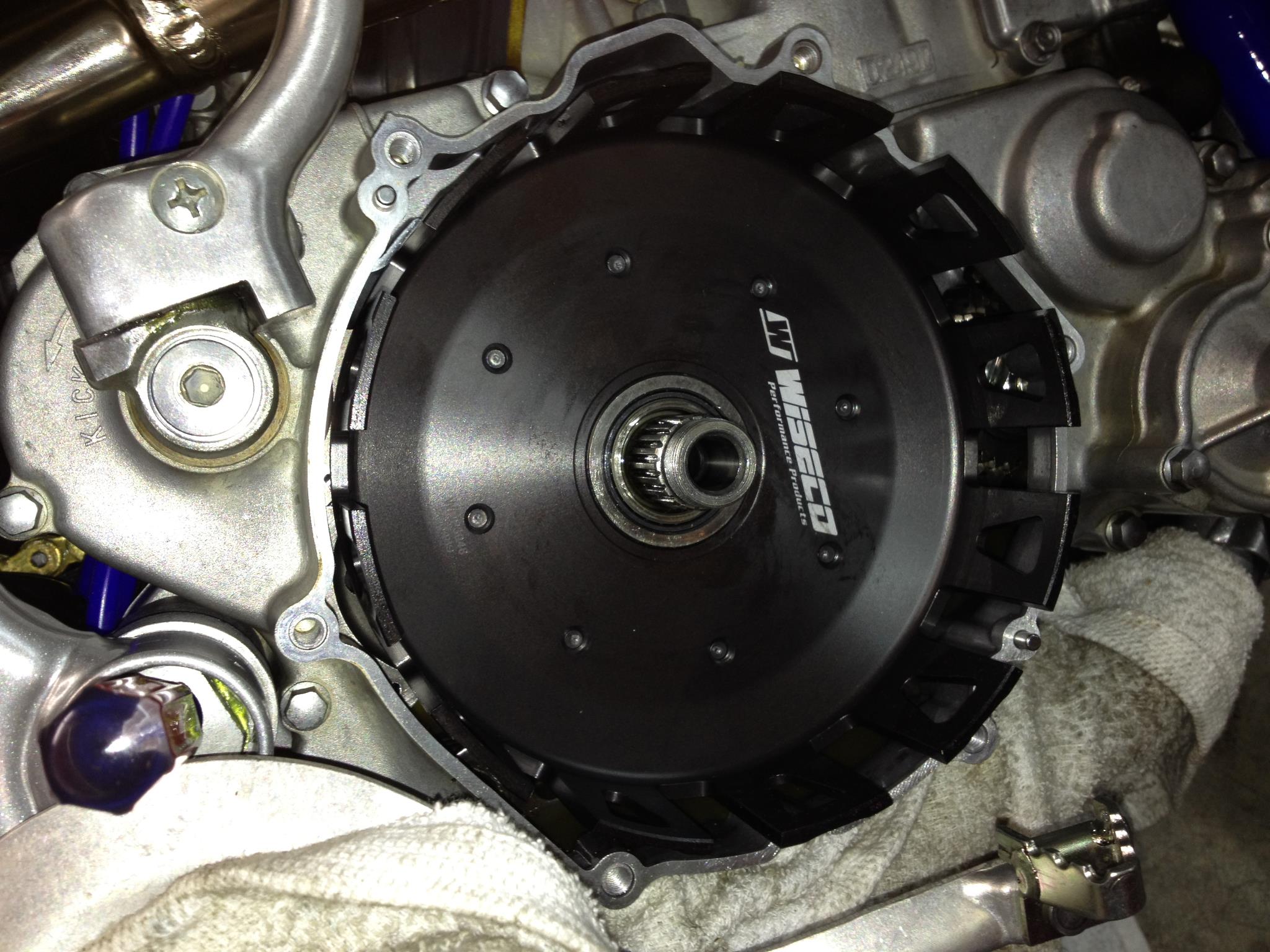
Part five of the CR250 engine build. This segment will cover the installation of the clutch pack, right side cover, power valve governor and water pump cover.
Before installing the power valve governor, coat the throwout balls and the rack with a 50/50 mixture of moly 60 grease and transmission oil. Place the 12mm plain washers on each end of the governor. Align the rack yoke with the bearing race on the governor and install as a unit in the right side center case.
Apply the same lubricant mixture from the previous step to the pinion shaft and bushing and insert into the right center case from the top until it meshes with the rack.
This picture shows the correct orientation of the pinion shaft before cylinder installation with down being the front of the case. Pack the area around the pinion shaft with grease to prevent air leaks.
To install the clutch outer (clutch basket), soak the bushing and double row needle bearing in transmission oil and install on the mainshaft end that protrudes from the right side center case.
Place the clutch outer on the mainshaft and turn it until it meshes with the idle wheel gear and the primary gear.
Coat the two dowel pins in transmission oil and install in the respective holes in the right center case. Hang a new gasket onto the dowels and install the right side cover onto the right center case.
I like to pre-soak the fiber clutch disc in transmission oil before installation. Find a suitable container that can be sealed against airborne contaminants, fill with transmission oil, place the fiber disc in the container and close the lid. Pre-soaking assures the disc are thoroughly saturated with oil and aids in clutch life and consistent clutch action.

This is an old salad container I swiped from the kitchen.
Next up is the clutch center. Install the large thrust washer then the clutch center followed by the small thrust washer, locking washer and nut. Clamp a clutch holder tool onto the clutch center and torque the nut to 60 lb.ft.
DO NOT TRY TO WEDGE A SCREWDRIVER OR SIMILAR DEVICE BETWEEN THE INNER AND OUTER FOR THIS.
You have a better than even chance of ruining one or both of the components if you do. Once the nut is torqued, use a pair of adjustable pliers to bend two of the locking tabs against the nut.
Load the clutch pack by alternating fiber and metal (or aluminum) disc, starting and ending with fiber. Here is an oportunity to “tune” your power delivery. If you ride on hard pack or otherwise have trouble getting the power to the ground without excessive wheelspin, install metal clutch plates instead of aluminum. The metal plates add rotational mass and will tame the “hit” a little. Also, bare aluminum plates shill and foul the transmission oil with aluminum particles in short order necessitating frequent oil changes. Some may have already noticed the brown metal plates in the previous picture. These are akadised aluminum which is a hard coating designed to give you the benefit of aluminum plates without the shilling.
Apply Moly 60 grease to both ends of the clutch actuating rod and insert it into the hole (line) in the mainshaft.
Install the pressure plate and six clutch springs
Install the six bolt/washers and tighten in three steps in a crisscrosspattern to 7 lb.ft.
Next up is the water pump. Coat the two dowel pins with oil and install. Place a new gasket on the dowel pins.
Place the separator plate over the first gasket.
Place a second gasket over the separator plate.
Now install the water pump cover and insert and tighten the bolts to 9 lb.ft. Install a new copper washer and the check bolt (black) and torque to 7 lb.ft.
Install and tighten the remaining right side cover bolts to 7 lb.ft. By the way, if you are using titanium bolts (like I am here), coat the bolts with a ti-prep grease to prevent dissimilar metal galling.


